In part 1 of this series, we looked at the strain gauge, which can be used to quantify how a test specimen deforms as a function of applied stress. We developed a Wheatstone-bridge circuit that makes use of strain-gauge elements in two of the bridge’s legs, as shown in Figure 1, a version of Figure 3 from part 1. Note that the strain-gauge elements take the place of resistors R2 and RX in Figure 2 from part 4 of our previous series on Kirchhoff’s laws.
Q: In Figure 1, it looks like you’ve changed some of the labels.
A: Right. I had been using VDMM to emphasize that we are using a modern digital multimeter (DMM) instead of a 19th-century galvanometer, which would have been used in early Wheatstone bridges. 19th-century galvanometers were quite useful in detecting zero current and voltage conditions, with applications extending to the decoding of transmitted signals in early trans-Atlantic telegraphy. However, such galvanometers were not good at quantifying non-zero levels, which modern instruments can do easily and accurately. In Figure 1, I’m using labels commonly found in strain-gauge literature. For example, I’ve changed VDMM to VO, for output voltage. In addition, I changed VIN to VEX, for excitation voltage. Finally, in the setup from our earlier series, VDMM varied inversely with RX. In Figure 1, I have reversed the meter polarity, so VO varies directly with RX and hence strain e.
To review, in Figure 1, RX is an active strain gauge, and R2 is a dummy strain gauge used for temperature compensation. Note that the long, thin wires of R2 are mounted perpendicular to the direction of tension, so their resistance is relatively unaffected by the strain.
Q: So, how do we calculate strain given VO?
A: From our previous series, we demonstrated how to calculate RX based on the voltage reading, with the DMM or output voltage equaling VV – VX. For the configuration shown in Figure 3 with the polarity switch,
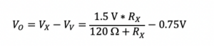
We can rearrange this equation as follows:
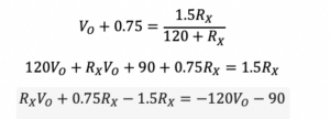
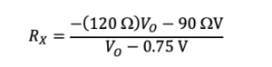
Then we can calculate RX as a function of VO:
Q: And how does strain relate to RX?
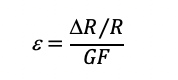
A: From part 1 of this series, we know that given a gauge factor GF, strain is
We also see that DR is RX – R2, where R2 equals the unstrained resistance of RX, or 120 W. So, given VO and a GF value of 2, we can directly calculate strain:
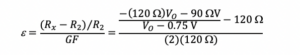
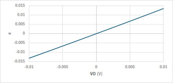
Figure 2 plots this equation for values of VO from -10 mV to +10 mV.
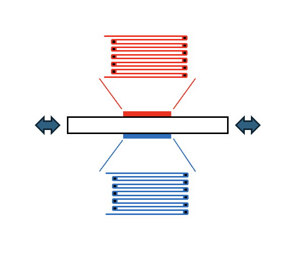
Q: Can we design a bridge configuration where both strain-gauge elements are active, and if so, what would be the advantages?
A: Figure 3 shows an alternative arrangement to Figure 1, with one strain gauge depicted in red placed at the top of a test specimen, while another depicted in blue is placed at the bottom, with the sense wires in both aligned with the direction of stress, so both are active.
Next time, we’ll take a look at how to apply this configuration and describe its benefits.
Related EEWorld Online content
Making sense of test circuits with Kirchhoff’s laws: part 4
How to use remote sensing for DC programmable power supplies
Things to know about multimeters
The first undersea transatlantic cable: An audacious project that (eventually) succeeded, Part 2
Wheatstone bridge, Part 1: Principles and basic applications
Stress & Strain, Part 1: fundamental principles