The antiresonance effect can be a bug or a feature. In the case of DC link capacitors in high-frequency converters, it’s a bug that can decrease performance. But antiresonance in ultrasonic transducer power supplies is a feature used for efficient, stable power delivery under varying loads.
Beyond the resonant frequency of a capacitor, parasitics in the package and other elements of equivalent series inductance (ESL) become significant and can cause the device to behave more inductively. Antiresonance occurs between the self-resonant frequencies (SRF) of different capacitors placed in parallel. It’s caused when one capacitor is operating above its resonant frequency (behaving inductively) while another is operating below its resonance (behaving capacitively).
In power converters and power distribution networks (PDNs), mixing capacitors like high-inductance and high-capacity electrolytic capacitors for low-frequency bulk storage and low-inductance ceramic capacitors for high-frequency noise management can be problematic.
Even with capacitors using the same or similar technologies, antiresonance can present a challenge for designers. The overlapping impedance profiles of capacitors with different values can cause impedance peaks and valleys at specific frequencies (Figure 1).
Factors in antiresonance
There are several factors to consider when working to minimize antiresonance. For example, using capacitors with large differences in values in parallel increases the chances for high antiresonance peaking.
ESL and equivalent series resistance (ESR) can also be important considerations. Higher ESL, including the capacitor and the contributions from the circuit board, can also lead to higher antiresonance peaking. Circuit board contributions to antiresonance can be mitigated by placing decoupling capacitors very close to the IC power pins, minimizing trace inductance.
ESR can have the reverse impact of ESL. High ESR capacitors, like aluminum electrolytics, can reduce the impact of antiresonance by damping the effect of smaller devices like ceramic capacitors with lower ESRs. In some cases, adding a resistor, especially when using capacitors with low ESRs, can also dampen the peaks.
Specialized capacitors like X2Y devices that combine two capacitors in a common package can also help minimize antiresonance issues.
DC links for EVs and renewable energy
DC link capacitors in inverters used for electric vehicle (EV) or renewable energy applications are often several hundred microfarad high-voltage polypropylene devices. The size of those capacitors can preclude placing them close to the power switches, resulting in antiresonance issues.
In high-frequency inverters using GaN or SiC switches, antiresonance can contribute to higher voltage overshoots, increasing the stress on the power switches. It can also demand the use of larger filters to meet electromagnetic compatibility (EMC) requirements. Another side-effect of antiresonance can be higher reactive currents that overheat snubber capacitors and reduce overall efficiency.
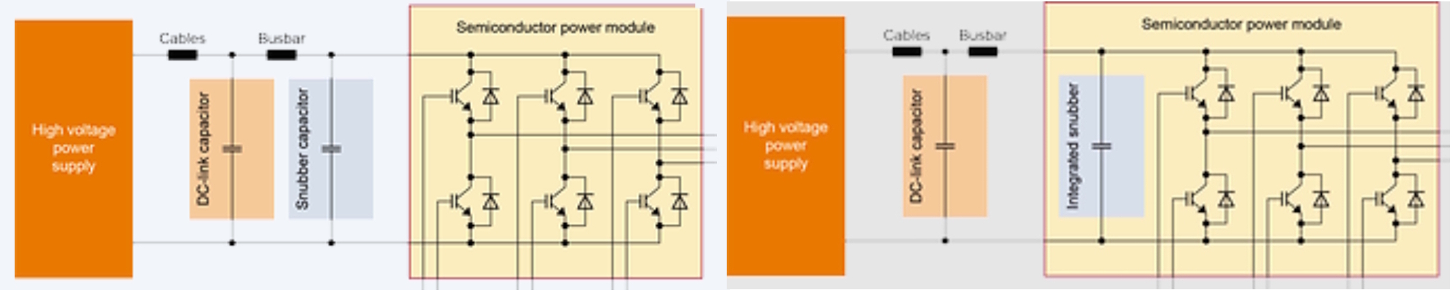
Employing a so-called hybrid architecture where the DC-link capacitance is split with a smaller capacitor placed directly adjacent to or inside the power module can be helpful (Figure 2). Another consideration is minimizing the contribution of the busbar inductance by using the shortest possible busbar.
Ultrasonic load requirements
Piezoelectric transducers are the most common type of ultrasonic device. They are inherently capacitive and used in medical imaging, non-destructive testing (NDT), cleaning, sensors, and actuator applications.
In ultrasonic applications, the antiresonance frequency is sometimes called the parallel frequency because it corresponds to the peak electrical impedance of the transducer, where the mechanical element and the clamping capacitor act as a parallel resonant circuit. It’s the point where the transducer draws minimum current.
As a result, the antiresonance frequency is used in applications like ultrasonic welding machines that are subject to wide load variations. In contrast, constant load applications, or applications with small load variations, like ultrasonic cleaning machines, operate at resonance, also called series-frequency (Figure 3).

Summary
Antiresonance in capacitors occurs when the capacitance and parasitic inductance form a parallel resonant circuit, resulting in an exceptionally high impedance (minimal current) at a specific frequency. It is a problem to be dealt with in many power converters and PDN designs. However, in the case of certain classes of ultrasonic transducer applications, like welders, it’s a positive contributor to circuit performance.
References
Capacitor Self-resonant Frequency and Signal Integrity, Cadence
CeraLink’s benefit in power module applications, TDK
Decoupling Capacitors for Power Distribution Systems with Multiple Power Supply Voltages, University of Rochester
How Power Integrity Suppresses Anti-Resonance Notches In Broadband PDNs?, Patsnap Eureka
Mastering EMI Control in PCB Design: Decoupling Strategies for PDN, Altium
Parallel Capacitors and the effect of Antiresonance, CompuPhase
Why do some ultrasonic equipment operate at resonance and others at antiresonance frequency?, ATCP Physical Engineering
Why is Antiresonance driving good and why could it be bad?, Ultrasonic Advisers
Related EEWorld Online content
Why won’t it work? A look at antiresonance
Characterize EMI from dc-dc converter ringing
What is a solid-state transformer?
What is a matrix converter used for?
How and where is vapor chamber cooling used?