Mechanical attachments for heat sinks depend on various factors, such as package type, pressure distribution, mechanical shock, vibrations, and geometry, to name a few. This FAQ discusses six mechanical attachments for heat sinks and the reasons why engineers should select them for specific cases.
Q: What are the primary considerations for reliable screw mounting?
A: Screw mounting is normally used for through-hole device packages such as the TO-220. For stable thermal contact, a plain washer is placed between the screw head and the mounting tab and is often used with a lock washer and nut. The effectiveness of this method depends on torque accuracy.
As shown in Figure 1, a proper mounting assembly utilizes a combination of plain and lock washers with appropriate torque to ensure consistent contact between the package, insulating media, and the heat sink.
Surface finish also affects performance. It is recommended that the heat sink’s flatness and roughness be maintained at a level of 10 μm to facilitate metal-to-metal contact. Self-tapping screws and pop rivets are avoided in these applications due to the risk of mechanical shock that can damage the silicon die. Such a move toward standardized torque limits ensures that the assembly remains within functional limits without compromising the internal structure.
Q: How do specialized spring clip systems improve BGA cooling?
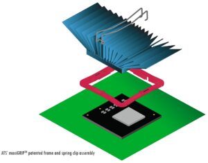
A: The “Double M” spring configuration provides a constant pressure across the component, as illustrated by the spring clip in Figure 2. One of the advantages here is that frame clips are normally rated UL-94V-0 for fire safety and provide thermal stability. Additionally, this mounting method allows for phase-change TIMs that can increase heat transfer efficiency compared to standard adhesive tapes.
These systems are often designed for component heights between 1.5 and 4.5 mm, ensuring they maintain pressure throughout the device’s lifecycle. Worth mentioning is that this method is reworkable, allowing heat sink removal and reattachment without affecting the PCB or adjacent surface-mount components.
Q: What benefits do push-type pins offer for uniform pressure distribution?
A: Push-type pins are a mechanical attachment used for lidless packages to transfer thermal loads to the PCB. Unlike single-point screw mounts, push pins apply force to multiple sides of the heat sink, as shown in Figure 3. This helps maintain a uniform bond line thickness and reduces the risk of die-edge chipping during the assembly process. Therefore, maintaining even pressure constitutes the primary goal of this mounting style.

To manage mechanical stress, engineers may use compressible foam pads on the heat sink for stability during installation. For variable-pitch BGA architectures, a constant compressive load between 10 and 50 psi is often specified. Handling lidless dies involves the use of tools, such as vacuum pencils with rubberized tips, to prevent micro-cracks.
Q: When should engineers utilize spring screws for pressure compensation?
A: For high-power lidded or lidless devices, spring screws (Figure 4) located at the four corners provide pressure compensation. These assemblies are associated with maintaining a pressure range of 20 to 50 psi. The required spring constant is calculated based on the target pressure and surface area. Also, Xilinx recommends an etched pattern on the heat sink contact surface with a coplanarity of 0.050 mm to allow micro-bubbles in the TIM to recede, which lowers contact resistance.

Board strain is normally monitored during assembly with the use of gauges to keep stress within 500 μstrain. This helps maintain board-level reliability and prevents solder joint failure due to board deflection. Because these systems apply force over a wide area, engineers must evaluate the need for backing plates or board bracing to ensure structural integrity and signal contact.
Q: How does center-loaded clip mounting optimize pressure distribution?
A: Clip mounting is frequently utilized in mass production to achieve superior alignment and uniform pressure distribution compared to traditional screw mounting. While screw mounting applies force at a “die center-off” position on the mounting tab, a center-loaded clip is positioned directly over the die, as shown in Figure 5.
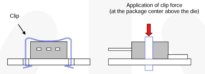
Clip mounting results in more even contact pressure and stable thermal resistance, even for convex geometries. Furthermore, the use of thermal grease fills any remaining microscopic air gaps, making the final assembly significantly less sensitive to torque variations and more resistant to mechanical vibration than screw-mounted alternatives.
Q: How do Z-Clip and anchor systems provide cost-effective anchoring?
A: Z-clip and anchor systems are mechanical attachments that utilize anchors mounted to the PCB. Figure 6 illustrates the practical application of a Z-clip on a heat sink. EZ-clips use a straight-down attachment method to minimize lateral stress on the TIM or die, which can occur with the twisting motion required by traditional clips. Anchors are available in solderless versions that snap into PCB slots or solder-type versions for permanent mounting.
Summary
Selecting the right heat sink mechanical attachment depends on the package type and environmental factors, including shock, vibration, and airflow. A right attachment helps ensure the thermal solution meets performance specifications. Now that these options are clearly defined, designers can evaluate which mounting style results in the best thermal performance for their specific device.
References
Thermal Management and Mechanical Handling for Lidless Flip Chip Ball-Grid Array Application Note, Altera Corporation
TN1225 – Mounting instructions for THD (through-hole device) packages, STMicroelectronics
Designing Heatsinks and Thermal Solutions for Xilinx Devices Application Note, AMD Xilinx
AN-4166 — Heat Sink Mounting Guide, Fairchild
maxiGRIP Heat Sink attachment, maxiGRIP
z-shape clip and anchor, Alpha Novatech
Related EE World content
Basics of cooling transistors, IGBTs, and power FETs with heat sinks and PCBs
How do thermal interface materials help in power electronics cooling?
Heat sinks, Part 2: Available components and performance
Basic principles of thermal management
Heat sinks, Part 1: Thermal principles