Board-to-board (BTB) connectors provide electrical connectivity and mechanical stability across stacked, parallel, or orthogonal printed circuit board (PCB) configurations.
Reliable connector engagement requires managing cumulative tolerances from PCB fabrication, component placement, solder reflow, and thermal cycling. Without effective alignment strategies, tolerance stack-up can prevent proper mating, stress solder joints, and degrade signal integrity.
This tutorial reviews the primary strategies for reliable BTB connector mating: float tolerance design, self-alignment features, mechanical keying and polarization, assembly process controls, and thermal expansion mitigation.
Float tolerance
Float tolerance describes the lateral and vertical displacement designed into a connector system to absorb misalignment between mating halves. This capability accommodates cumulative tolerances from PCB fabrication, component placement, and reflow shift without imposing tight upstream manufacturing constraints.
Modern floating BTB connectors compensate across three axes. Typical X- and Y-axis (lateral) float ranges from ±0.5 mm to ±0.6 mm, while some high-performance designs extend to ±0.7 mm to ±0.8 mm. Z-axis (height) float typically reaches ±0.5 mm to ±0.6 mm.
As shown in Figure 1, some floating BTB connectors provide up to ±0.7 mm of lateral compensation in the X and Y directions.
Floating capability is implemented through two primary approaches. Spring-loaded contacts introduce compliance within the contact element. Two-piece housing designs place the contact carrier inside an outer shell, where springs or elastomeric elements allow controlled movement while maintaining positional centering. Dual-beam or multi-finger contacts maintain reliable electrical engagement despite positional offset.
Float tolerance becomes critical when multiple connector pairs share the same board interface. Cumulative placement variation across several connectors can exceed 1 mm at the outermost connector. Floating connectors absorb this stack-up, improve assembly yield, and reduce reliance on tight board-level fixturing.
Self-alignment features
Self-alignment mechanisms extend beyond float tolerance by guiding initial connector engagement. Large guide pins on the header engage corresponding receptacles before electrical contacts meet, correcting initial misalignment during mating. This leaves only residual positional variation for the floating contacts to absorb.
As shown in Figure 2, large guide features can provide coarse self-alignment before the floating contact system absorbs the remaining positional variation.

In high-reliability designs, guide pin alignment tolerance exceeds the float range of the electrical contacts. This creates a two-stage correction process: coarse alignment during engagement, followed by fine absorption through float. The approach is particularly important in automated assembly, where pick-and-place equipment may have limited positional accuracy.
Tapered and chamfered entry geometries complement guide pins by progressively redirecting the mating connector during insertion. These features reduce assembly precision requirements and accommodate minor angular misalignment without damaging contacts.
In RF and compression-mount connectors, additional alignment features support post-assembly verification. Traditional designs conceal the relationship between the center conductor and the PCB landing pad after installation.
Alignment grooves milled into the connector body correspond with PCB fiducials, providing visual confirmation that the connector is centered on its landing pad. This verification is particularly important in systems operating above roughly 20 GHz, where sub-millimeter misalignment can introduce impedance discontinuities and degrade signal integrity.
Mechanical keying and polarization
Keying and polarization play complementary roles in BTB connector systems. Keying prevents mating between similar connectors that should not be interconnected. Polarization ensures that matched connectors mate only in the proper orientation, preventing 180-degree rotation or other positional errors. Together, these features implement design-for-manufacturing principles by preventing incorrect assembly.
Several mechanical approaches implement these functions. Polarization key tabs extend from the connector housing and align with corresponding cutouts in the mating connector. Asymmetric housing profiles prevent reverse or rotated mating through geometry alone.
Differentiated end features, where each end of a connector carries a distinct cutout size or shape, enforce single-orientation mating. Offset side keys and blanking pins, where selected contact positions are blocked in defined patterns, provide additional orientation control.
Polarization is especially important in blind-mating applications such as mezzanine card installations, stacked assemblies with limited access, and robotic assembly processes. Because operators cannot visually confirm alignment during insertion, the connector geometry must enforce correct orientation. In many designs, the mechanically keyed shape simultaneously functions as the polarization feature.
In systems with similar connectors that must not be cross-mated, additional differentiation methods provide a clear visual and mechanical distinction. Unique key patterns, color coding, labeled markings, and size differentiation prevent incorrect mating between connectors. Combining keying with polarization significantly reduces assembly errors in complex multi-board systems.
Assembly considerations
Reliable BTB mating begins with accurate connector placement during PCB assembly. Datum-based placement references solder pads to a common datum, minimizing cumulative offset across the board.
Fiducial-based alignment directs pick-and-place equipment to use PCB surface fiducials near connector landing pads, reducing errors from metal etching variation. Machine vision systems provide real-time position verification before reflow, allowing correction of placement errors before soldering fixes the connector in place.
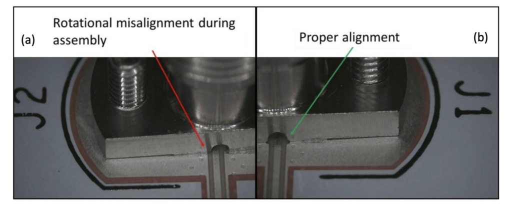
As shown in Figure 3, even minor rotational misalignment during assembly can shift the connector body off its intended position, reinforcing the need for fiducial-based placement and pre-reflow verification.
In multi-connector systems, locating pegs assist coplanarity during reflow but can contribute to tolerance stack-up when several connectors share the board. In these cases, designers often use connectors without alignment pins or drill oversized holes where polarization is required. Precision machine placement then determines the final connector position.
Mating force management is also important. Excessive insertion force can damage PCBs and solder joints, while insufficient engagement produces unreliable connections. Rolled contact surfaces, tapered lead-in features, and spring-loaded contacts with optimized normal force reduce insertion and extraction forces while maintaining reliable electrical contact.
When assembling multi-board stacks, bottom-up assembly allows gravity to assist alignment. Sequential connector mating, engaging one connector pair at a time rather than all simultaneously, reduces peak insertion force across the board set. Securing hardware such as jackscrews and standoffs should be positioned near connector systems rather than at board corners to localize mechanical stress and minimize PCB flexure during thermal cycling.
Thermal expansion
PCBs exhibit anisotropic thermal expansion. In the X-Y plane, woven glass reinforcement constrains FR-4 expansion to approximately 13 to 17 ppm/°C. In the Z-axis, the same material expands at roughly 55 to 60 ppm/°C below its glass transition temperature.
Connector housings made from liquid crystal polymer (LCP), polyphenylene sulfide (PPS), or high-temperature nylon expand at 15 to 30 ppm/°C depending on material composition and glass fill. This coefficient-of-thermal-expansion (CTE) mismatch creates relative motion between mating connector halves during thermal cycling.
Float tolerance is therefore the primary design tool for accommodating thermally induced displacement. Connectors with ±0.7 mm to ±0.8 mm lateral float absorb significant in-plane expansion without compromising electrical contact or inducing solder-joint stress.
Additional strategies reduce thermal displacement and its mechanical effects. Designers typically designate one board mounting location as the rigid constraint while using shoulder bolts with clearance holes at all other mounting points.
Over-constraint forces PCB bending stress into solder joints during thermal expansion rather than allowing the board to expand freely. Slotted mounting holes at non-rigid attachment points permit in-plane expansion while constraining out-of-plane motion. Slots should be oriented radially from the rigid attachment point.
Connector placement relative to the rigid constraint also affects thermal behavior. Connectors located near the constraint point experience minimal relative displacement, while those positioned farther away experience larger thermally induced motion. These locations benefit from connectors with the widest available float range.
For automotive and industrial applications, thermal cycling validation from −40 °C to +125 °C with continuous contact-resistance monitoring confirms that the connector and solder-joint system maintain electrical and mechanical integrity throughout the expected service life.
Summary
Reliable BTB connector alignment requires coordinated control of manufacturing tolerances, assembly practices, and thermal expansion. Float tolerance and self-alignment features manage positional variation during mating, while mechanical keying and polarization prevent incorrect orientation. Assembly practices and thermal constraint strategies ensure connectors maintain reliable electrical and mechanical performance across the system lifecycle.
References
FloatCombo™ 0.50mm Floating Board-to-Board Connectors with Power Pin, Amphenol
Types of Polarization Techniques for Secure Mating, Amphenol
Board-to-board Connectors: How to Optimize Embedded System Design, Meritec
Slimstack Floating Board-to-Board Connectors, Molex
Tolerance Stack Up in Multi-Connector Applications, Samtec
New Alignment Features Ensure Precision Alignment in Test & Measurement Applications, Samtec
Exploring the Key to Enhanced Efficiency in Connector Assembly, Molex
What are Polarization and Keying in Connectors, Harwin
Related EEWorld content
Be Aware of Connector Mating-Cycle Limits
Beyond the Datasheet: How Digital Tools Are Reshaping Connector Engineering
Derating Connector Current Ratings for Real-World PCB Power Designs
From Bolts to Bots: Solving the Connector Puzzle in Robotics
Board-to-board Connectors Feature EMI Shielding