This final part continues the look at MIL-STD-1553B with an overview of formats and protocols, as well as available hardware and development/debug tools.
Formats and protocol
Q: What is the basic signal format described by the standard?
A: A Manchester code is used to present both clock and data on the same wire pair and to eliminate any DC component in the signal (which cannot pass through the transformers), with a peak-to-peak output voltage at a transmitter of 18 to 27 volts.
Q: What is the communications sequence cycle?
A: MIL-STD-1553B is a deterministic protocol, not a probabilistic one. All communication on the bus is under the control of the Bus Controller using commands from the BC to the RTs to receive or transmit. Transmissions onto the data bus are accessible to the BC and all connected RTs.
Q: How are messages framed?
A: Messages consist of one or more 16-bit words (command, data, or status), with each bit transmitted as a 0.5 microsecond high/0.5 microsecond low for a logical 1 and the reverse sequence for a logical 0. Each word is preceded by a 3-microsecond synchronization pulse of 1.5 microsecond low plus 1.5 microsecond high for data words and the opposite for command and status words, then followed by an odd parity bit.
Q: Is that all there is?
A: Absolutely not. The entire sequence is a complicated back-and-forth with multiple modes, all using a variation of a master-slave protocol. For example, if an RT needs to pass data to another RT, it must first await a query from the BC, then respond and send data to the BC, which passes that data to the other RT.
Devices have to start transmitting their response to a valid command within 4 to 12 microseconds. The complicated sequences ensure that the terminal is functioning and able to receive data. Adding a status word at the end of a data transfer sequence ensures that the data has been received and that the result of the data transfer is acceptable, thus providing a high level of data integrity.
Q: What does the overall system timing look like?
A: The standard does not define detailed timing for specific transfers — that’s left up to the system designers who invariably need flexibility. In most designs, the software runs through a list of major and minor cycles of tasks (roughly like a programmable logic controller) with major cycles done more frequently than the minor ones.
Major cycles often have a 50-hertz cycle, while minor and sub-minor cycles can have 25 or 12.5 Hz timing. There is a provision for an RT to “raise its hand” and request attention from the BC as well.
Products and tools
The MIL-STD-1553B market is a big and vital area for many products. Various vendors specialize in satisfying all needs from small functions to larger, more complete ones.
Q: Are “mainline” IC vendors in this market?
A: Yes, but serving a market focused on mil/aero/hi-rel installations is a challenge. For example, Intel offered the highly integrated M82553 Protocol Management Unit (PMU) IC in the 2008-2009 time frame, shown in Figure 1, but discontinued it after a few years.
Q: Who are some non-IC vendors, less-widely known vendors of MIL-STD-1553B products?
A: Among the leading long-term vendors with comprehensive product offerings are United Electronic Industries (UEI) and Data Device Corporation (DDC).
Q: Do these companies offer only hardware?
A: No, that alone is not sufficient. They also offer development tools, simulators, and software modules that simplify the process of integrating their products into a full MIL-STD-1553B system. Also, there are specialized bus analyzers with protocol-decoding and analysis capability that facilitate observing signal-transfer characteristics and much more for this bus, seen in Figure 2.

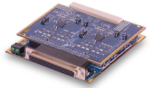
Q: What are some of the products they offer?
A: As one example, the DNx-1553-553 PC card from UEI is a two-channel MIL-STD-1553-to-Ethernet converter shown in Figure 3. Each channel is fully independent and provides a complete, dual-redundant MIL-STD-1553 interface. Each channel is transformer-coupled, though direct coupling is available as an option. Each channel may be independently configured as a Bus Controller (BC), a Remote Terminal (RT), or a Bus Monitor (BM). As a Bus Controller, the board supports all standard transfer and messaging modes.
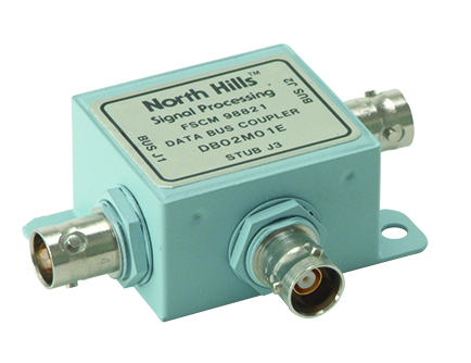
Q: What about interface components?
A: DDC/North Hills has the DB01M01E single-stub couplers, seen in Figure 4, as well as multiple-stub couplers. These units provide 55 dB common mode rejection and are fabricated using a hot-tinned cold-rolled steel case, which is solder-sealed for superior environmental, EMI, and corrosion protection.
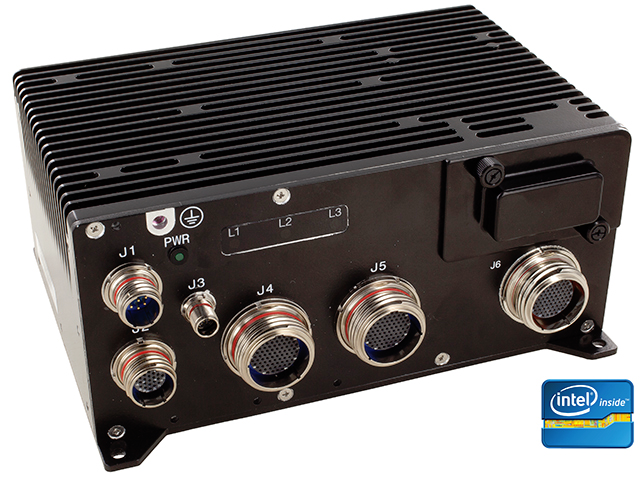
Q: Are boards and subassemblies the only form factors that are available?
A: No, complete computer chassis are available, such as the DDC Rugged Avionics Interface Computer (AIC) shown in Figure 5.
This AIC provides a flexible and scalable platform that supports a wide range of data network communications. Among its many modes, its Protocol Conversion Mode uses a bridging software development kit that allows users to easily create embedded software on the AIC to autonomously forward data between MIL-STD-1553, ARINC 429, and Ethernet Interfaces.
Q: What field test equipment is available in addition to the protocol analyzers used for product development and debug?
A: The DBT300 Handheld Tester is able to quickly troubleshoot or test a MIL-STD-1553B Data Bus Network, shown in Figure 6. It can detect shorts, opens, crossovers, and shorts-to-shield on the bus and stubs. The testers are designed so the user can perform these checks from the Line Replaceable Unit (LRU) ends of the stub cables. It also has the capability to measure Return Loss and Insertion Loss to easily benchmark network characteristics.

Q: Where does MIL-STD-1553B go from here?
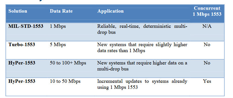
A: While many aircraft and other applications mix MIL-STD-1553B with other, higher-speed busses such as Ethernet, there are also efforts to upgrade the original standard, as indicated in Figure 7. Of course, there are issues of upward quality, reliability, ruggedness, and more to be addressed and resolved.
Fiber-optic versions are also being explored due to the many advantages they can bring, but no firm standard has yet been established.
References
MIL-STD-1553 Tutorial & Reference, United Electronic Industries (UEI)
Review and Rational of MIL-STD-1553 A and B, Data Device Corporation
MIL-STD-1553B, Data Device Corporation
Adding MIL-STD-1553 to any platform made easy, Data Device Corporation
High Performance 1553, Data Device Corporation
MIL-STD-1553 Evolves with the Times, Data Device Corporation
MIL-STD-1553 Goes Commercial, Data Device Corporation
A Practical Approach to Commercial Aircraft Data Buses, Data Device Corporation
MIL-STD-1553, Wikipedia
Manage MIL-STD-1553B bus with just one chip, Gale/Cengage Group
Intel M82553 Protocol Management Unit (PMU), Datasheet Archive
MIL-HDBK-1553A Multiplex Applications Handbook MIL-STD-1553, Test Systems
Selecting RF Cabling for Defense, Space, and Other Harsh Environments: Coax vs Twinax vs Triax, Cinch Connectivity Solutions, Inc.
Twinaxial cabling, Wikipedia
Related EE World content
FAQ on cable impedance: 50 Ω versus 75 Ω
Understanding the MIL-STD-1553B bus, Connector Tips
Cinch Connectivity expands its MIL-STD-1533B bus coupler line, Connector Tips
What are triaxial cables?, Wire and Cable Tips
Understanding the MIL-STD-1553B bus
Making measurements of MIL-STD-1553 connections
The basics of bus analyzers