Engineers are problem solvers. It’s what we do. When working on a project at your bench, you probably have the usual collection of hand tools, test equipment, and a soldering station or two. Sometimes you need more than these tools. Sometimes, you have to solve a practical problem before solving the problem at hand. That’s where adding and building jigs, holders, compartments, and other things can help.
Some common add-ons are the alligator clip “helping hands” (Figure 1). The clips let you hold PCBs, wires, connectors, or components, which certainly helps when soldering. A magnifying glass enhances the experience, especially when working with small parts.
Figure 2 shows a PCB vice, another device that can hold a PCB during soldering. Several such tools are on the market. See EEWorld’s review of the PCBite kit from Sensepeak.
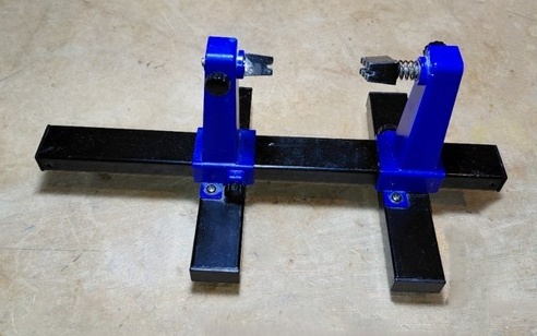
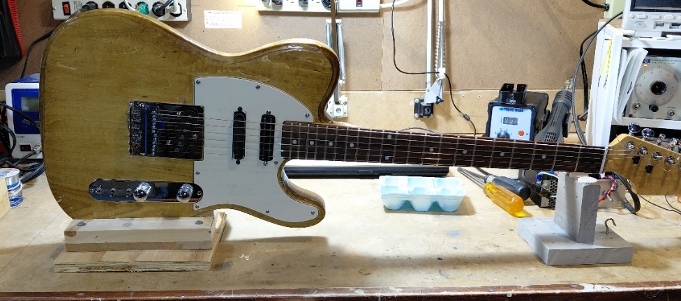
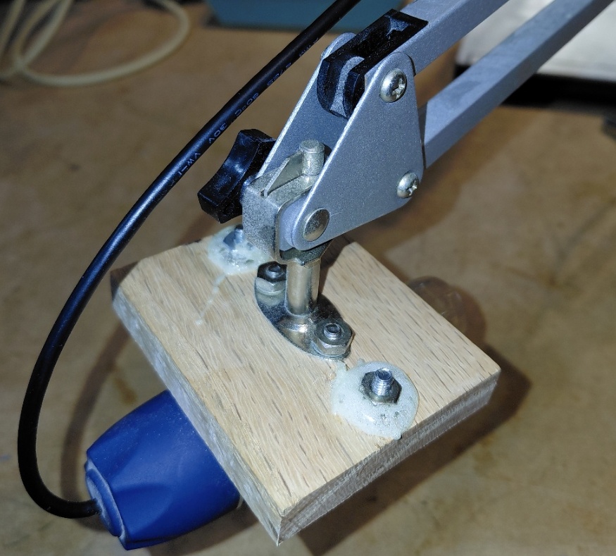
You may also need special tools, stands, or jigs to assist in construction and testing. One of my projects involves adding on-board electronics to electric guitars. I do enough of this work that I don’t want to prop up the guitar body on whatever cardboard or plastic project boxes I have in my lab and start soldering. Instead, I built a couple of simple jigs. One allows me to hold the guitar upside down with strings facing the bench but not touching anything (so the strings aren’t muted). See Figure 3 and Figure 4. This makes it easy to tinker with the circuit boards I’m installing on the back of the body. A second jig allows me to clamp the guitar body sideways (without marring the body) when that’s needed. See Figure 5.
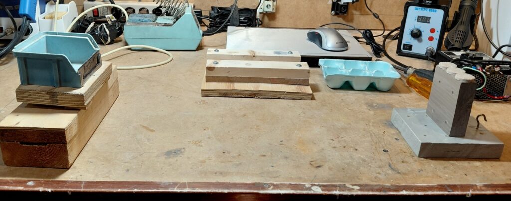
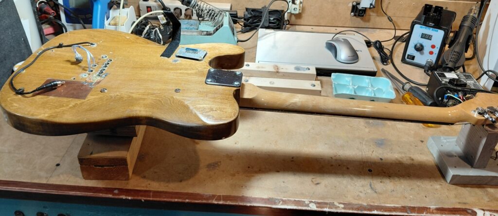
Another handy device is a compartmentalized component and hardware holder: an egg carton. There’s one visible in Figures 3 through 5. These help keep mounting hardware from vanishing under the various bench equipment or, worse yet, into the vacuum cleaner.
Preventing ESD damage
Let’s now consider assembling a PC board populated with surface-mount components that might be damaged by electrostatic discharge (ESD). Let’s assume you know that ESD should be mitigated with a conductive mat, upon which you place your PCB. You could buy a conductive mat, but an inexpensive mat can be equipped with a piece of black conductive IC foam, shown in Figure 6. Note the clip lead that attaches and grounds the mat. I added a small piece of brass shim stock to make it easier to clip onto the mat without chewing through it.
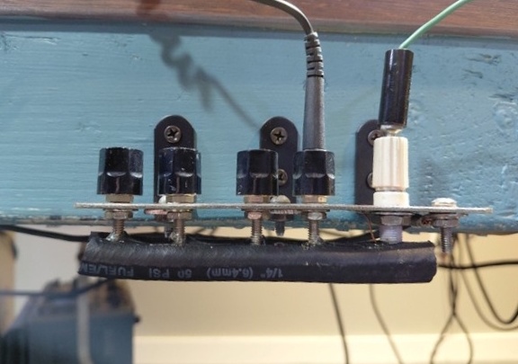
On my bench, I added the grounding connectors (banana jacks), also visible in Figure 6. The plate is connected to the same earth ground connection that my circuit breaker panel uses. It’s a combination of a ground stake and a connection to the incoming copper water supply line. I’m assuming there will never be any high magnitude ground fault currents flowing while I’m working at my bench, so my ground connection should really be at a (true) earth potential.
I also realized I would scrape my knees on the tips of the banana connectors on the underside of my ground block, so I added a piece of ¼-in. rubber tubing (slit the entire length and attached with hot melt adhesive), shown in Figure 7.
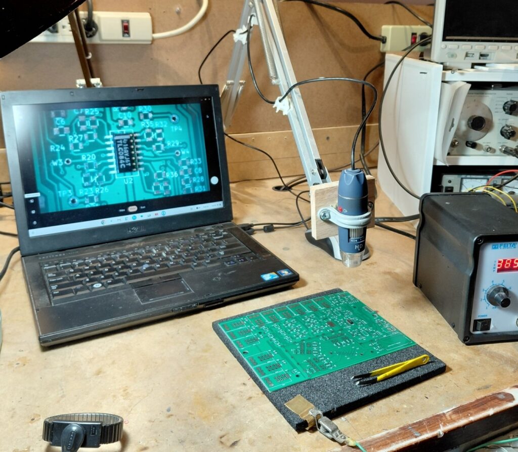
Besides these ESD features, you will likely want a magnifier to help place tiny surface-mount components. A magnifying glass can provide some help, but I prefer a video microscope. These are available in various magnification levels and price points. I’m using an inexpensive device from Amazon with a mag range of 40 X to 1000 X. I mounted it on a used bench light boom I got from Goodwill. See Figure 8. For the video monitor, I’m using a laptop computer that originally ran Windows 10. Since that’s no longer supported, I wiped the hard drive and converted the laptop to a Chromebook.
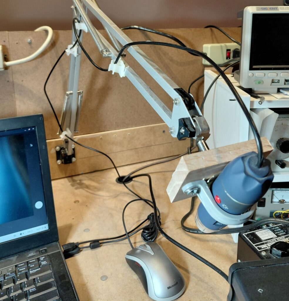
Sometimes, you need a camera to document your work or to see things on a large screen. You surely need something to hold the camera, such as a boom or tripod. Figures 9 and 10 show the details of how I attached a camera to the end of the boom.
Hold components in place while soldering
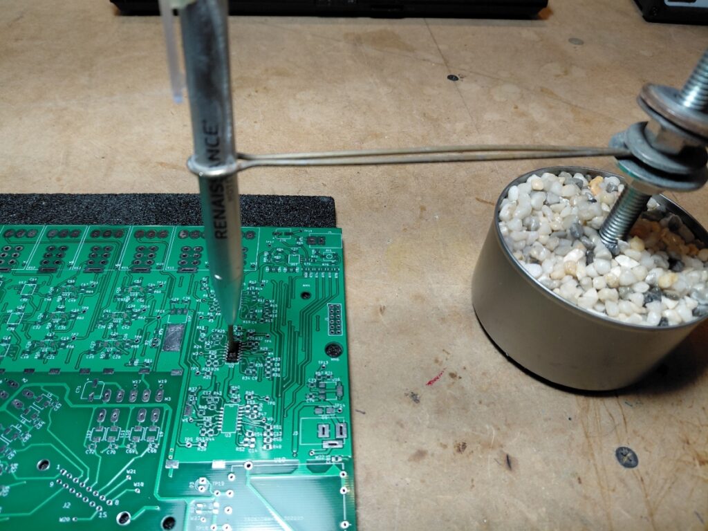
For around $30, I had a useful setup that mostly made soldering tiny components with my hot air soldering station pretty easy. Occasionally, when attaching parts using a soldering iron and 0.020″ solder, I found I would sometimes bump the component out of position. For those occasions, I built a tool to hold the component while soldering the first few pins. See Figure 11. I built this using a tuna fish can (without the tuna), some pea gravel, epoxy glue (acting as a sort of potting compound), a piece of threaded stock plus nuts and washers, a piece of 14 AWG copper wire, and an old ballpoint pen to act as a spring-loaded pin. I changed the ink cartridge and spring locations around to get the desired spring action. This applies just enough pressure to keep things in place.
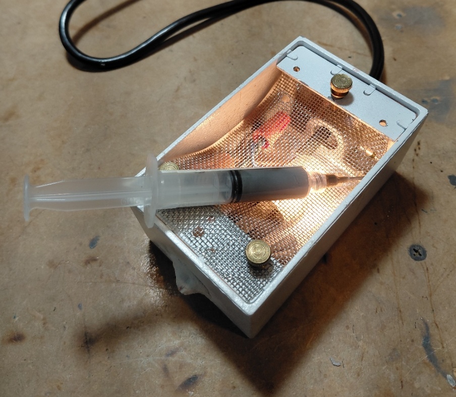
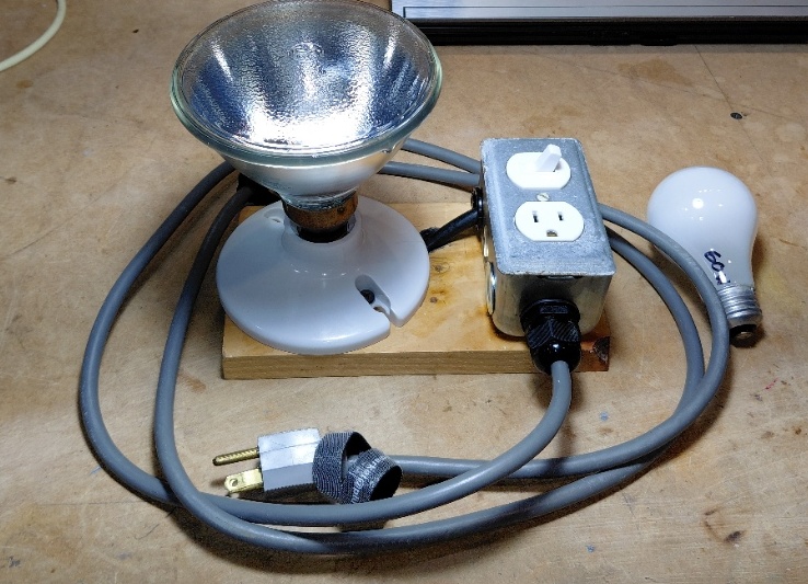
For soldering with hot air, solder paste is the preferred method. I was using some paste that had much higher viscosity than I would have liked, but I didn’t want to waste it, so I built a small heater box to keep it warm, which lowered its viscosity. See Figure 12. It’s simply a spare electrical junction box, a [grounded] power cord, a 15 W candelabra light bulb, and a scrap of stainless-steel screen. Once again, a low-cost solution.
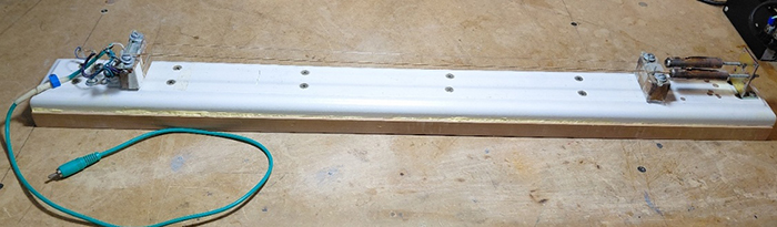
Returning to my engineering work on guitars and guitar electronics, I needed a way to evaluate different styles of pickups and methods of inducing sympathetic vibration into the strings. Referring to Figure 13, I built a jig with some used strings, a piece of MDF (medium-density fiberboard), a piece of pine trim board, miscellaneous bits of hardware, small blocks of (scrap) oak (acting as bridges), and a piezo (PZ) disc salvaged from a PZ beeper.
In use, I placed my electromagnetic drivers beneath the strings at different points between the left and right bridges and noted their effectiveness as drivers.
When testing line-powered equipment, you may find that the equipment suffers from internal short circuits. This problem commonly arises from power transformers with shorted turns within windings, shorted rectifier diodes, shorted filter capacitors, or other supply rail shorts in the equipment under test (EUT). We need a good way to detect and analyze these problems without repeatedly blowing the EUT’s built-in fuses or tripping its circuit breakers.
The clever way is by using a Variac to power the EUT and inserting a medium to high wattage incandescent light bulb in series with the power being supplied from the Variac. For line-powered equipment, we don’t want to use a suicide cord and a bunch of Radio Shack clip leads. A more elegant solution is shown in Figure 14.
With the appropriate wattage bulb, normal current draw causes little heating of the bulb’s filament. Based on the positive temperature coefficient of tungsten, the barely warm filament’s voltage drop is very low, and the EUT receives close to the full line voltage. You can crank up the line voltage slowly, and if excessive current flows, you’ll know because the light bulb (but not the fuses) will glow brightly.
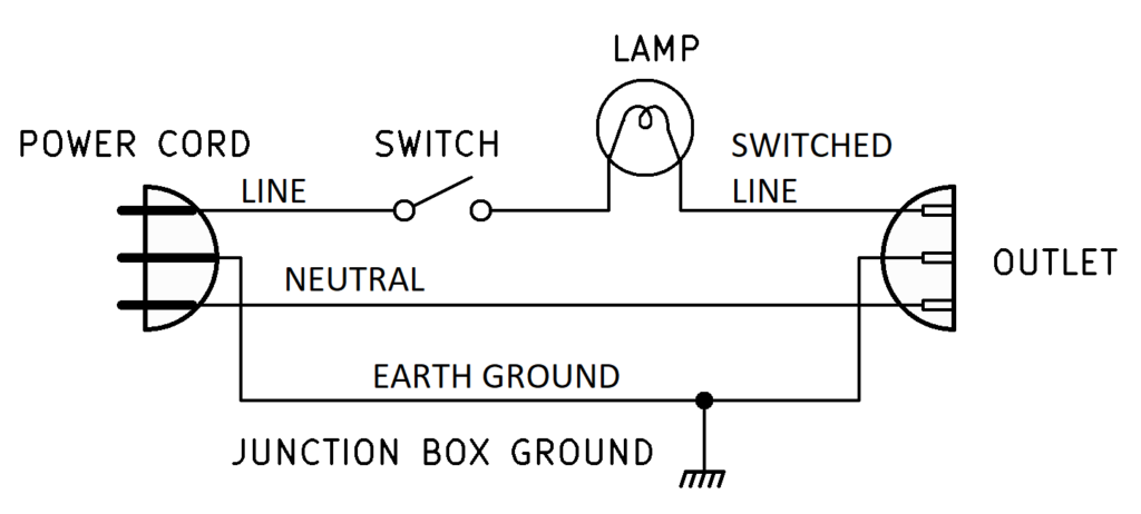
The schematic for this device (Figure 15), like many of my preceding test jigs, is simple. I recommend having several different bulb wattages on hand, from 40 W to 250 W. You should procure several now before they become obsolete.
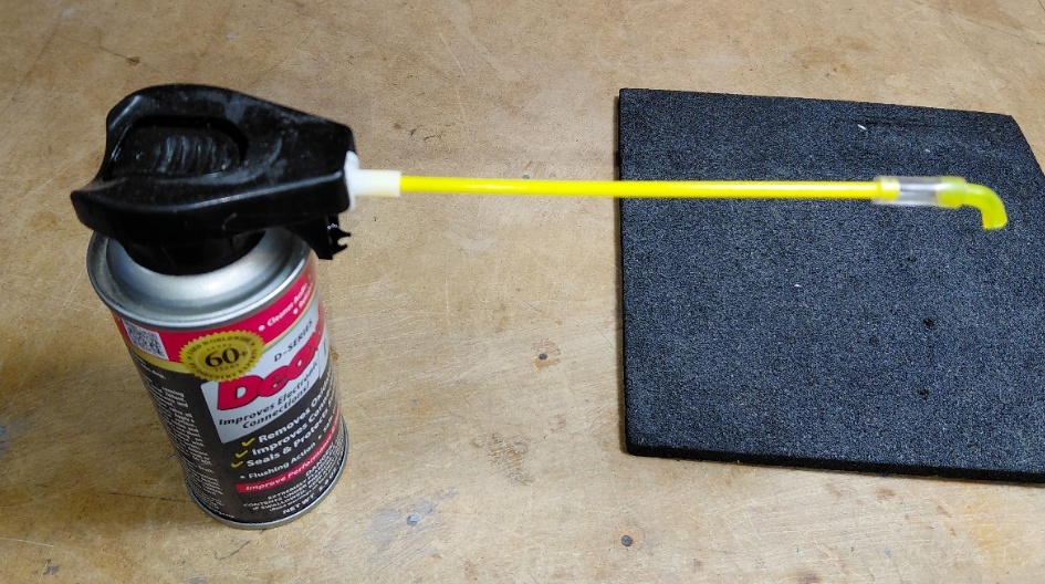
Lastly, consider those times when you’re trying to spray contact cleaner into a volume control whose opening is obscured due to its mounting position. Trying to bend the small-gauge tubing that comes with the spray can rarely work — it will probably kink. I worked around this by fabricating an elbow from some scraps of larger-gauge plastic tubing. I was able to bend it by carefully heating it with my hot-air soldering station. The larger gauge made it far less likely to pinch shut at the bend. See Figure 16.
In part 2, we’ll take a close look at some of my custom-built test jigs to simplify some of the audio testing that I do.
What test jigs or time-saving tools have you devised? Tell us in the comments.