Electric vehicle (EV) architectures operating at 800 V and above deliver measurable efficiency gains by reducing current for a given power level. Because resistive losses scale with the square of current, lower current reduces conduction losses across cables, busbars, and switching components. At the same time, higher bus voltage shifts design constraints across the entire high-voltage system.
This article outlines how 800 V+ architectures reshape connector and contactor requirements, from creepage and clearance to arc suppression. It also discusses insulation coordination, contactor behavior, thermal performance, and contact resistance. Long-term reliability and qualification are addressed as well.
Creepage, clearance, and insulation coordination
Creepage and clearance distances scale directly with working voltage. Moving from 400 V to 800 V DC can nearly double minimum spacings for a given insulation category, pollution degree, and material group.
Under IEC 60664-1, an 800 V DC bus in automotive conditions with pollution degree 2 and material group IIIa typically requires creepage distances in the 8 mm range for basic insulation. Required clearances are comparable but vary with overvoltage category and impulse test voltage. Achieving these distances within compact connector and contactor housings necessitates internal barriers, ribs, and grooved surfaces that extend creepage paths without increasing package size.
In addition to geometric spacing, solid insulation must withstand steady-state voltages from 800 V to 1000 V DC as well as transient overvoltages, thermal cycling, and mechanical stress over vehicle life.
Connector housings and inserts typically use glass-reinforced PBT, PA66, and related high-temperature polyamides selected for dimensional stability, high comparative tracking index, and dielectric strength at elevated temperatures. Specialized PBT and PA grades with CTI ratings up to Class A 600 V and stable volume resistivity enable compact 800 V to 1000 V designs that resist tracking and surface erosion in humid or contaminated environments.
In higher-temperature zones, PPS and aromatic polyamides such as PA6T and PA9T provide additional thermal margin, although PPS often requires additives to approach the CTI performance of leading PBT and PA grades. Altitude further reduces air dielectric strength, increasing required clearance distances. For vehicle programs targeting elevations of 3000 m to 4000 m, IEC 60664-1 correction factors can increase baseline clearance values by 14 to 29 percent.
Arc suppression and contactor behavior
While insulation coordination defines spacing and material requirements, switching performance introduces a separate set of constraints. At 800 V+ DC, arc initiation becomes easier and arc extinction more difficult than at 400 V. Consequently, contactor design shifts from simple mechanical switching to engineered arc control.
As shown in Figure 1, high-voltage EV DC contactors use sealed, gas-filled chambers, typically containing inert gas, to increase dielectric strength of the medium and reduce arc length and persistence.
Designers further extend and steer the arc using double-break contacts and magnetic blowout systems, driving it into cooler regions where it extinguishes before full contact separation.
Contactor designs divide into polarized and non-polarized types, each with distinct tradeoffs at higher voltage. As shown in Figure 2, polarized contactors orient blowout magnets to control arc motion for current flowing in a defined direction, achieving higher make-break ratings and longer electrical life in the rated direction.
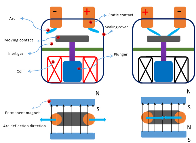
When current reverses, breaking capacity and cycle life can drop by roughly 30 to 50 percent relative to the rated direction.
Non-polarized contactors use symmetrical magnet arrangements to maintain similar breaking capability in either direction, typically at the cost of roughly 50 percent lower electrical cycle life than a polarized unit in its optimal direction.
For most EV main pack contactors, where load-break current direction is predictable, polarized types are preferred above roughly 350 V because they provide stronger arc control and longer service life per unit volume. Non-polarized designs are used in applications with frequent high-current bidirectional switching or architectures that can’t guarantee current direction at opening.
Insulation coordination within the contactor follows IEC 60664-1 principles similar to those applied to connectors, with additional requirements for specified making and breaking capacity at defined voltage and inductance to verify arc performance over service life.
Thermal performance and contact resistance
Beyond switching performance, sustained current introduces additional thermal constraints. Moving from 400 V to 800 V halves current for a given power level, reducing ideal conduction losses in cables, busbars, and contacts by roughly 75 percent under I²R scaling.
In practice, OEMs often increase total system power concurrently. For example, systems rated at 200 kW at 400 V may scale to 300 to 400 kW at 800 V, so absolute current and thermal stress on connectors and contactors remain high.
High-voltage EV connectors routinely carry hundreds of amperes in compact housings, where even milliohm-level contact resistance generates significant power loss and temperature rise. Industry targets for contact resistance in battery, inverter, and fast-charging paths typically remain below 1 to 2 milliohms at continuous currents above 300 A.
Even at these resistance levels, operating temperatures approaching 125 °C accelerate contact resistance drift through annealing, fretting corrosion, and oxidation. Thermal control measures include conservative current derating relative to nominal ratings, high-conductivity copper alloys, silver or tin plating, and optimized crimp geometry.
In high-power modules, some designs integrate cooling interfaces near connector and contactor terminals to maintain thermal margin under sustained load. Automotive connector standards require initial contact resistance measurement followed by re-measurement after vibration, thermal cycling, and corrosion exposure to verify long-term stability and reliability.
Long-term reliability and qualification
At 800 V+, any localized increase in contact resistance from fretting damage, partial corrosion, or a degraded crimp raises local temperature while reducing insulation margin. In humid or contaminated environments, this interaction can promote partial discharge or surface tracking along insulating paths that would otherwise remain within specification.
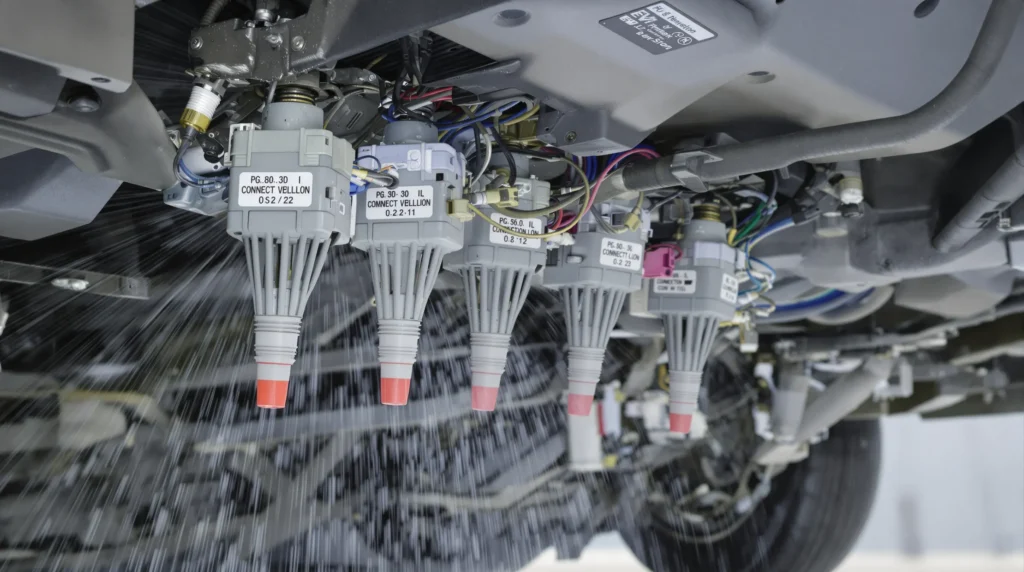
Fast switching transitions in silicon carbide (SiC) inverters further raise electrical stress on insulating surfaces, increasing partial discharge risk at 800 V. As shown in Figure 3, IP6K9K sealing, gel ingress barriers, and gas-tight terminal designs mitigate this risk by excluding moisture and contaminants from contact interfaces.
Qualification protocols for 800 V connectors and contactors verify performance before and after endurance cycling, load switching, temperature-humidity bias, salt spray, and high-vibration testing. For contactors, endurance testing covers continuous current, short-time withstand under crash and fault conditions, and thousands of load-break operations. Post-test evaluation verifies contact resistance, weld tendency, insulation resistance, and dielectric withstand.
Designs using silver-based contact alloys and controlled contact force limit erosion and welding over the required duty cycle. Connector locking mechanisms, position assurance features, and secondary terminal locks prevent partial mating and terminal back-out, maintaining electrical integrity across vehicle life.
As 800 V+ architectures increase power density and compress packaging, engineers integrate connector and contactor temperature rise, derating, and resistance drift into the overall powertrain thermal budget.
Summary
Shifting to 800 V+ EV architectures redirects connector and contactor design toward insulation coordination, arc suppression, and long-term contact stability. Expanded spacing, engineered arc control, and rigorous qualification under electrical and environmental stress define 800 V automotive performance.
References
Insulation Coordination in Automotive Power Module (IEC60664-1:2020), Infineon
Switching Polarized and Non Polarized DC Contactors, DuraKool
Demystifying Clearance and Creepage Distance for High Voltage End Equipment, Texas Instruments
Designing High Voltage Contactors (HVC) for Electric Vehicles and Renewable Energy Systems: Key Considerations, WeVolver
High-Voltage EV Contactors: Polarized vs. Non-polarized, Charged EVs
The Impact of 800V Architectures on EV Thermal Management Components, Faistgroup
High-Voltage EV Connectors: Key to Reliable Power Transmission, Jonhon EV
DC Contactor Relays, TTI
An Introduction to New Energy High-Voltage Connectors and Key Points for Plastic Material Selection, Gudmold
Determining CTI to Ensure EV Safety When Using High-CTI HV Connectors, Envalior
Requirements for High-Voltage Cable Insulation in Electric Vehicle Wire Harness Systems, GVEI
Requirements for the Insulation Layer of EV High Voltage Cables, Guchen Connector
Related EEWorld Online content
What Engineering Requirements Shape EV High-Voltage Connectors and Contactors?
New Contactor Bridges Legacy and 800-V EV Architectures
The Shift to 800-V EV Platforms
New GaN Platform Targets 800-V EV Powertrains and Ultra-Fast Charging Infrastructure
How Do Onboard Chargers Differ Between 400 and 800-V EV Architectures?