Inrush current represents one of the most common yet overlooked challenges in power electronics design. These sudden current surges can exceed normal operating levels by 10 to 100 times, lasting only milliseconds but carrying enough energy to damage components or trigger unwanted circuit breaker trips that frustrate users and compromise system reliability.
Inrush characteristics by application
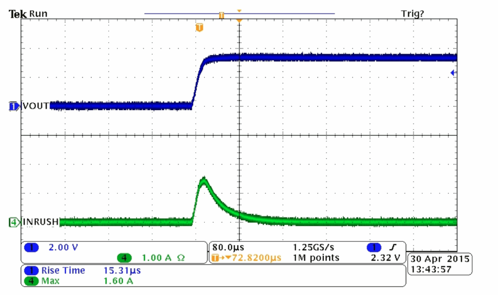
Different types of loads create distinctly different inrush patterns, each requiring specific consideration during design. Capacitive loads, such as input filter capacitors in power supplies, generate relatively predictable exponential charging currents. Modern high-density capacitor designs commonly produce initial surges of 20 to 40 times their steady-state current, though their brief duration typically makes them easier to manage than other load types. Figure 1 is an example of how capacitance affects inrush magnitude.
Transformer-based equipment presents more challenging scenarios, especially with modern high-efficiency cores that can generate inrush currents up to 30 times their rated levels compared to about 18 times for older transformer designs. The worst-case conditions occur when the circuit energizes at peak voltage, creating magnetic saturation that drives these extreme current levels. Interestingly, this peak inrush doesn’t happen every time the equipment turns on, either. It’s more of a statistical event that occurs roughly once in every five to ten startups.
Switching power supplies create some of the most severe inrush conditions because they rectify incoming power directly without the current-limiting effect of an input transformer. This design approach can produce initial surges of 40 to 100 times the normal operating current, typically lasting for several cycles of the AC input frequency. Motor applications vary widely, with single-phase motors generally creating the most sustained inrush conditions, often drawing six to eight times their running current for nearly a full second during startup.
Measuring inrush current effectively
Accurate measurement proves challenging because standard electrical meters simply cannot respond quickly enough to capture millisecond-duration events. Even with the necessary oscilloscope-based measurement systems, common current probes often saturate and provide misleadingly low readings when currents exceed about 12 to 14 times their rated capacity.
The most reliable approach involves using precision current-sensing resistors placed directly in the circuit path, then measuring the voltage drop across these resistors with an oscilloscope. This technique provides accurate amplitude and timing information essential for proper protection design. Modern simulation tools have also become quite sophisticated, allowing for the modeling of expected inrush behavior before building prototypes, though careful attention to component models and parasitic effects remains crucial for accurate results.
For transformer applications, remember that inrush magnitude varies with factors like residual magnetism in the core and the exact timing of switch closure relative to the AC voltage waveform. This variability means that testing must include multiple turn-on events under various conditions to capture worst-case scenarios.
Choosing protection strategies
Protection approaches generally fall into three categories: passive current limiting, active soft-start circuits, and hybrid combinations. Passive techniques using components like NTC thermistors remain popular for smaller systems because of their simplicity and low cost. These devices start with high resistance when cold, limiting initial current flow, then decrease in resistance as they heat up from the current flow itself. This approach works well for systems up to about 350 W, though it is important to consider that rapid on-off cycling can reduce their effectiveness.
Active soft-start circuits offer more precise control by using semiconductor switches to gradually ramp up current or voltage. Modern integrated solutions include smart load switches with programmable current limits and digital power controllers that can adapt their behavior based on load conditions. These approaches typically cost more but provide superior protection and can eliminate the steady-state power losses associated with passive methods.
Hybrid approaches attempt to capture the benefits of both techniques by using passive current limiting during startup, then bypassing the limiting element once steady-state operation begins. This eliminates ongoing power losses while maintaining startup protection, though at the cost of additional circuit complexity.
Circuit breaker selection and system coordination
Selecting appropriate circuit breakers requires understanding both the magnitude and duration of expected inrush currents. Standard breakers may trip unnecessarily if their instantaneous trip settings fall below peak inrush levels, but setting them too high compromises protection against actual fault conditions.

Many applications benefit from breakers specifically designed with inrush tolerance. These devices can withstand short-duration high-current pulses without tripping while still providing normal overcurrent protection. For switching power supplies, engineers typically select breakers rated at two to three times the steady-state current with high pulse tolerance characteristics.
The timing aspects matter as much as the current magnitude. Transformer inrush typically concentrates in the first few milliseconds, while motor starting currents may persist for hundreds of milliseconds or longer. Understanding these timing differences helps in selecting breakers with appropriate delay characteristics.
Standards and practical considerations
Various industry standards address inrush current effects, particularly regarding power quality and electromagnetic compatibility. These standards recognize that inrush events can create voltage disturbances affecting other equipment and may generate electromagnetic interference that impacts sensitive electronics.
Compliance considerations often influence design decisions, especially in commercial and industrial applications where equipment must coexist with other systems. It is important to consider these requirements early in the design process rather than attempting to address them after the fact.
Best practices
Successful inrush management starts with early analysis and continues through comprehensive testing. It is advisable to characterize expected inrush behavior during initial design phases using simulation tools and prototype measurements. Design verification must include worst-case conditions such as high line voltages, temperature extremes, and the statistical peak events that may occur infrequently but with significant impact.
System-level considerations become particularly important in applications with multiple loads or hot-swap capabilities, where sequential startup events can create complex interactions. Testing should include repeated on-off cycles under various operating conditions to ensure reliable performance across the full range of expected usage patterns.
The evolution toward more efficient power electronics continues to present new challenges, but also new opportunities for intelligent inrush management using advanced control techniques and wide-bandgap semiconductors. Success requires balancing protection requirements with cost, size, and performance objectives while maintaining focus on long-term reliability and user satisfaction.
Editor’ note: This article is an updated version originally published on EEWorld here.